Chamberlain 3585 3/4 User Manual
Browse online or download User Manual for Garage Door Opener Chamberlain 3585 3/4. Chamberlain 3585 3/4 User's Manual [ja] [zh]
- Page / 40
- Table of contents
- BOOKMARKS
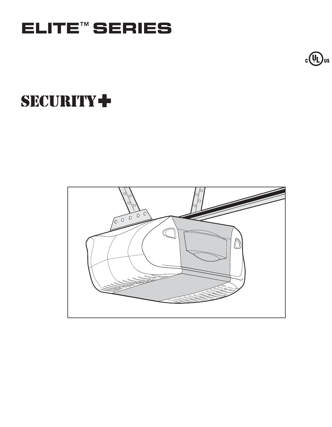
- GARAGE DOOR OPENER 1
- Model 3585 3/4 HP 1
- Owner’s Manual 1
- TABLE OF CONTENTS 2
- INTRODUCTION 2
- Preparing your garage door 3
- Tools needed 3
- Planning 4
- Carton Inventory 5
- Motor unit 6
- Sprocket 6
- INSTALLATION STEP 1 8
- INSTALLATION STEP 2 9
- INSTALLATION STEP 3 10
- INSTALLATION STEP 4 11
- INSTALLATION STEP 5 12
- INSTALLATION STEP 6 13
- INSTALLATION STEP 7 14
- INSTALLATION STEP 8 14
- INSTALLATION STEP 9 15
- INSTALLATION STEP 10 16
- 7/16" 18
- INSTALLATION STEP 11 19
- INSTALLATION STEP 12 21
- ADJUSTMENT STEP 1 23
- ADJUSTMENT STEP 2 24
- ADJUSTMENT STEP 3 25
- ADJUSTMENT STEP 4 25
- IMPORTANT SAFETY INSTRUCTIONS 26
- WARNINGWARNING 26
- CARE OF YOUR OPENER 29
- HAVING A PROBLEM? 30
- Diagnostic Chart 31
- PROGRAMMING 33
- REPAIR PARTS 35
- KEY PART 36
- NO. NO. DESCRIPTION 36
- ACCESSORIES 37
- LIFTMASTER 40
- SERVICE IS 40
- HOW TO ORDER 40
Summary of Contents
The Chamberlain Group, Inc.845 Larch AvenueElmhurst, Illinois 60126-1196www.liftmaster.comGARAGE DOOR OPENERModel 3585 3/4 HPFor Residential Use Only
HeaderBracketBelt PulleyBracketTemporarySupportHeader WallGarageDoorClevis Pin5/16"x2-3/4"Ring FastenerHeader BracketBelt PulleyBracketRailC
11ONE-PIECE DOOR WITHOUT TRACKA 2x4 on its side is convenient for setting an idealdoor-to-rail distance. • Remove foam packaging.• Raise the opener on
12INSTALLATION STEP 5Hang the OpenerThree representative installations are shown. Yours maybe different. Hanging brackets should be angled (Figure 1)t
13INSTALLATION STEP 6Install the Door ControlLocate door control within sight of door, at a minimumheight of 5' (1.5 m) where small children cann
14INSTALLATION STEP 7Install the Light • Press the release tabs on both sides of lens. Gentlyrotate lens back and downward until the lens hinge is int
15INSTALLATION STEP 9Electrical RequirementsTo avoid installation difficulties, do not run the openerat this time.To reduce the risk of electric shock
16Facing the door from inside the garageINSTALLATION STEP 10Install The Protector System®The safety reversing sensor must be connected andaligned corr
17INSTALLING THE BRACKETSBe sure power to the opener is disconnected. Installand align the brackets so the sensors will face each otheracross the gara
Invisible Light BeamProtection AreaSafety Reversing SensorSafety Reversing SensorConnect Wire toOpener Quick-Connect TerminalsBell WireBell WireFinish
19Fiberglass, aluminum or lightweight steel garage doors WILLREQUIRE reinforcement BEFORE installation of door bracket.Contact your door manufacturer
2Introduction 2-5Safety symbol and signal word review . . . . . . . . . . . . . .2Preparing your garage door . . . . . . . . . . . . . . . . . . . .
Header WallVerticalCenterline ofGarage DoorFinished CeilingOptionalPlacementof DoorBracketHeaderBracketDoorBracket2x4 SupportFor a door with no expose
21INSTALLATION STEP 12Connect Door Arm to TrolleyFollow instructions which apply to your door type asillustrated below and on the following page.SECTI
22ALL ONE-PIECE DOORS1. Assemble the door arm, Figure 4:• Fasten the straight and curved door arm sectionstogether to the longest possible length (wit
23ADJUSTMENT STEP 1Adjust the UP and DOWN Travel LimitsLimit adjustment settings regulate the points at which thedoor will stop when moving up or down
24ADJUSTMENT STEP 2Adjust the ForceForce adjustment controls are located on the back panelof the motor unit. Force adjustment settings regulate theamo
25Without a properly installed safety reversal system, persons(particularly small children) could be SERIOUSLY INJURED orKILLED by a closing garage do
26OPERATIONIMPORTANT SAFETY INSTRUCTIONSTo reduce the risk of SEVERE INJURY or DEATH:Using Your Garage Door OpenerYour Security✚®opener and hand-held
27Using the Wall-Mounted Door ControlTHE SMART CONTROL PANELTMPress the push bar to open or close the door. Press againto reverse the doorduring the c
The 3V2016 lithium batteries for the opener and LEDlights (marked “LED and Opener Battery”) should last 5years. The 3V2450 lithium battery for the pro
29CARE OF YOUR OPENERLIMIT AND FORCE ADJUSTMENTS:Weather conditions may causesome minor changes in dooroperation requiring some re-adjustments, partic
3To prevent damage to garage door and opener:• ALWAYS disable locks BEFORE installing and operating theopener. • ONLY operate garage door opener at 12
30HAVING A PROBLEM?1. My door will not close and the light bulbs blink onmy motor unit: The safety reversing sensor must beconnected and aligned corre
Bell WireSafety Reversing SensorKG13975KG13975DiagnosticsLocated OnMotor Unit"Learn" Button LED or Diagnostic LED Installed Safety Rev
32Meaning: This message will appear if the Safety Reversing Sensors are out ofalignment, if they are blocked or if the wiring is disconnected. To clea
33*3-Button RemotesIf provided with your garage door opener, the large buttonis factory programmed to operate it. Additional buttons onany Security✚®3
34To Add, Reprogram or Change a Keyless Entry PINNOTE: Your new Keyless Entry must be programmed to operate your garage door opener.USING THE “LEARN”
811126NOTICEUPCEILING MOUNT ONLY9715101314LOCKLIGHT342Installation Parts25613784Rail Assembly Parts35REPAIR PARTSKEY PARTNO. NO. DESCRIPTION1 4A1008 M
36Motor Unit Assembly PartsDNUPBrownWire(Down)ContactLIMIT SWITCH ASSEMBLYGreyWireYellowWire(Up)ContactCenter LimitContactDriveGear243115198A175189101
37ACCESSORIES 370LM41A52811702LMOutside Quick Release:Required for a garage with NO accessdoor. Enables homeowner to opengarage door manually from out
38NOTES
39NOTES
FINISHED CEILINGSupport bracket& fasteninghardware is required.See page 12.SafetyReversing SensorHeaderWallAccess DoorSafety Reversing SensorGap b
© 2007, The Chamberlain Group, Inc.114A3396C All Rights ReservedLIFTMASTER®SERVICE ISON CALLOUR LARGE SERVICE ORGANIZATIONSPANS AMERICAINSTALLATION AN
5Your garage door opener is packaged in two cartonswhich contain the motor unit and all parts illustratedbelow. Accessories will depend on the model p
To avoid SERIOUS damage to opener, ONLY usebolts/fasteners mounted in top of motor unit.ASSEMBLY STEP 1Attach the Rail to the Motor UnitTo avoid insta
7INSTALLATIONIMPORTANT INSTALLATION INSTRUCTIONSTo reduce the risk of SEVERE INJURY or DEATH:WARNINGWARNINGWARNINGWARNING1. READ AND FOLLOW ALL INSTAL
8INSTALLATION STEP 1Determine the Header BracketLocationInstallation procedures vary according to garage doortypes. Follow the instructions which appl
Lag Screw5/16"-9x1-5/8"HARDWARE SHOWN ACTUAL SIZELag Screws5/16"-9x1-5/8"Highest Point of Garage Door TravelVerticalCenterline ofG
Related products and manuals for Garage Door Opener Chamberlain 3585 3/4
 (1 pages)
 (2 pages)
 (4 pages)
© 2020, manymanuals.com. All rights reserved. | 1.931 s |
 Manymanuals.com
 Manymanuals.de
 Manymanuals.fr
 Manymanuals.it
 Manymanuals.pl
 Manymanuals.cz
 Manymanuals.es
 Manymanuals-pt.com
Comments to this Manuals